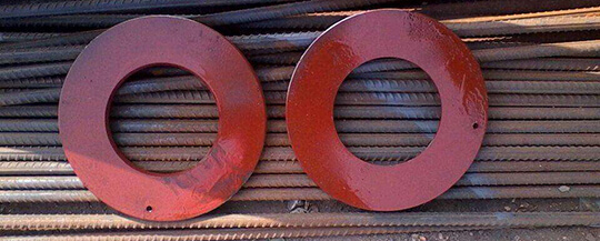
1.1 This standard specifies the type, size and technical requirements of the reinforcement circle for the reinforcement of the steel pressure register shell opening.
1.2 When this standard is used for reinforcement of steel pressure vessel shell openings with reinforcement ring structure, the following conditions shall be met at the same time:
a) The design pressure of the vessel is less than 6.4MPa;
b) The design temperature of the vessel should not be 350℃;
c) The nominal thickness of the opening of the container shell δn≤38mm;
d) The lower limit of the standard tensile strength of the container shell steel is not more than 5 MPa;
e) The thickness of the reinforcing ring should not be more than 1.5 times the nominal thickness of the opening of the shell.
1.3 This standard does not recommend containers made of chromium-molybdenum steel, nor is it recommended for containers with extremely hazardous and highly hazardous media.
1.4. This standard does not apply to vessels subjected to fatigue loads.
2 Normative references
The clauses in the following documents become clauses of this standard after being quoted in this standard. For dated reference documents, all subsequent amendments (excluding errata content) or revisions do not apply to this standard. However, all parties that have reached an agreement based on this standard are encouraged to study whether the latest versions of these documents can be used. The latest version of undated reference documents is applicable to this standard.
GB 150-1998 Steel pressure vessel
GB/T 197-1981 common thread tolerance and fit
GB/T 1804-2000 General tolerance Tolerance of linear and angular dimensions without tolerance
JB 4708-2000 steel pressure vessel welding procedure qualification
JB 4730-1994 pressure vessel non-destructive testing
3 Symbols
D1——inner diameter of reinforcing ring, mm;
D2——outer diameter of reinforcing ring, mm;
dN——nominal diameter of joint pipe, mm;
d0.一一outer diameter of joint pipe, mm;
δc.——the thickness of the reinforcing ring, mm;
δα.一一nominal thickness of the shell opening, mm;
δn1.一一nominal thickness of joint pipe, mm.
4 Type and size
According to the requirements of the welded joint structure of the reinforcing ring, the groove of the reinforcing ring is divided into five forms: A, B, C, D, and E
Type A is suitable for fillet welding structures where the shell is an inner dial;
Type B is suitable for the partial penetration structure with the inner groove of the shell;
Type C is suitable for full penetration structure with outer grooved shell;
Type D is suitable for full penetration structure with inner grooved shell;
Type E is suitable for full penetration structure with inner grooved shell.
5 Technical requirements
5.1 The thickness of the reinforcing ring is calculated according to the relevant regulations of GB 150-1998
5.2 The welded joints connecting the reinforcement drawing to the shell and connecting pipes should be designed by themselves according to the design conditions and structural requirements. The welded joints used for low-temperature pressure vessels must adopt a full penetration structure.
5.3 The material of the reinforcing ring is generally the same as that of the shell, and should meet the requirements of the corresponding material standards.
5.4 The reinforcing ring can be made of a whole plate or divided into blocks in a radial direction. The reinforcement of radial segmented joints is only allowed to be used in situations where the integral reinforcement ring cannot be installed. After the splicing and welding, the surface of the weld seam should be polished smooth and flush with the base material of the reinforcement ring, according to JB4730-1994 Carry out ultrasonic testing, level II is qualified.
5.5 The butt welded joints of the shell covered by the reinforcing ring and the welding joints connected to the shell and the connecting pipe shall be polished to be flush with the base material before the reinforcing ring is installed. The shape of the reinforcing ring shall also be the same as that of the reinforced part. The shell matches to ensure that the reinforcement ring fits with the shell.
5.6 When installing the reinforcing ring, pay attention to placing the screw hole in the lowest position of the shell. The machining accuracy of the screw hole is in accordance with the 7H level in GB/T197-1981; the manufacturing tolerance of the rest of the reinforcing ring is in accordance with GB/T1804-2000 M level in.
5.7 The welding of the reinforcing ring, the shell and the connecting pipe shall be carried out by the welding process qualified by JB4708-2000. Before welding, the rust, welding slag, oil, moisture and other dirt in the groove should be removed.
5.8 After the reinforcement ring is welded, the weld seam of the reinforcement ring should be inspected. There should be no defects such as cracks, pores, slag inclusions, etc.; if necessary, magnetic particle inspection or penetration inspection should be done according to JB4730-1994, and the level 1 is qualified. The shape of the weld should be polished to a smooth transition.
5.9 Pass the compressed air of 0.4MPa~0.5MPa through the M10 screw hole to check the quality of the welding seam of the reinforcing ring. There should be no leakage in the fillet welding seam.
